Radio cables aren't sexy. Nobody's writing hit songs about coaxial lines or dreaming about RF connectors at night. And yet, here we are - you're studying radio communication, which means you're gonna spend more time thinking about these things than you ever imagined. Trust me on this one.
I remember my first lab session back when I was learning the ropes. The instructor handed me what looked like a garden hose with metal bits on the ends and said, "Don't lose signal." That's it. No explanation of impedance matching, no discussion of standing wave ratios. Just "don't lose signal" - which is kind of like telling someone to bake a soufflé without mentioning the oven temperature. Check out this thread if you don’t believe me.
The thing is, radio cables do one job: they move electromagnetic energy from Point A to Point B without spilling too much along the way. Sounds simple, right? It's anything but. You're dealing with invisible waves that bounce, reflect, and attenuate (that's fancy talk for "get weaker") based on factors you can't see with the naked eye.
Let's talk coax first, because you'll see these everywhere. The design is almost comically simple: a central conductor surrounded by insulation, wrapped in a braided shield, all tucked inside an outer jacket. It's like those Russian nesting dolls, except each layer serves a purpose beyond looking cute on a shelf. That shield? It's there to keep outside interference from mucking up your signal. Radio frequency interference is everywhere these days - your microwave, your neighbor's WiFi, even some LED bulbs throw out RF noise like confetti at a parade.
Here's where things get interesting: impedance. No, don't glaze over yet! This matters more than you think. Most radio gear operates at 50 ohms, which means your cable better matches that value or you're asking for trouble. Mismatched impedance creates reflections; the signal bounces back toward the source instead of traveling to your antenna. You end up with what we call standing waves, and they're terrible.
I've seen students (and honestly, some professionals who should know better) grab whatever cable was lying around because "it's all the same, right?" Wrong. Dead wrong. A 75-ohm cable might look identical to a 50-ohm cable, but swap them and watch your transmission quality tank faster than the Titanic.
Twin-lead cable is another beast entirely. Picture two parallel wires held apart by insulation – it looks a bit like a ladder made of wire and plastic. Old-school antenna enthusiasts swear by this stuff, and they've got a point. Twin-lead has lower loss than coax at certain frequencies, and it's cheaper to manufacture. The downside? It's more susceptible to interference and weather conditions. Moisture loves to mess with twin-lead performance, which is why you don't see it used as much in modern installations.
Now, attenuation - there's that word again. Every cable loses signal as the electromagnetic energy travels through it. Physics is undefeated on this front. Longer cables mean more loss. Higher frequencies mean more loss. Cheaper cables with inferior shielding and conductors? You guessed it - more loss. This is why choosing the right cable for your frequency range isn't just good practice; it's mandatory if you want your system to actually work.
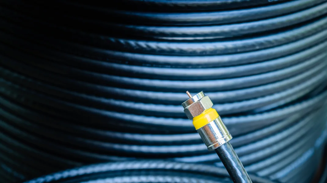
Connectors are where theory meets reality in the most frustrating ways imaginable. You can have the perfect cable, matched impedance, the ideal length, and then ruin everything with a poorly installed connector. BNC connectors are common in lab settings because they twist-lock into place (hard to accidentally disconnect mid-experiment). SMA connectors show up in higher-frequency applications. N-type connectors handle more power and weather better than most alternatives.
Each connector type has a specific impedance value and frequency range. Mixing and matching isn't creative problem-solving - it's self-sabotage. I once watched someone try to adapt an SMA connector to a BNC using three different adapters daisy-chained together. The signal loss was catastrophic, but hey, it physically connected! That's not how this works.
Shielding effectiveness varies wildly between cable types. Cheap coax might use aluminum foil and a sparse braid. Quality cable employs multiple layers of shielding - maybe foil plus a tight copper braid, sometimes even double-shielded designs. Radio frequency interference doesn't play fair, and skimping on shielding to save a few bucks will haunt you during every transmission.
Environmental factors matter too. Ultraviolet radiation from sunlight degrades cable jackets over time. Temperature extremes make materials expand and contract, potentially creating gaps in shielding. Moisture finds its way into the smallest openings, corroding connectors and altering the electrical properties of insulation. Cables rated for outdoor use cost more, but they're engineered to handle these challenges.
Frequency range compatibility is another thing nobody mentions until you've already bought the wrong cable. A cable that performs beautifully at HF frequencies might be completely inadequate for UHF work. The physical construction - conductor size, insulation type, shielding configuration - all these factors determine where a cable performs best. Manufacturers publish specification sheets for a reason. Read them.
Flexibility seems like a minor concern until you're trying to route cables through tight spaces or around corners. Rigid cable maintains better electrical properties but becomes a nightmare during installation. Flexible cable is easier to work with, but often has higher loss figures. It's always a tradeoff, always a compromise.
Power handling capacity flies under the radar for beginners, but it shouldn't. Pump too much RF power through an inadequate cable and bad things happen. The cable heats up. The insulation can melt. In extreme cases, you might even start a fire. This isn't hypothetical - I've seen charred cables that were asked to handle power levels they were never designed for.
Installation technique deserves an entire course unto itself. Sharp bends create impedance discontinuities. Loose connectors introduce signal loss. Over-tightened connectors damage threads and crush insulation. The sweet spot exists, but finding it requires practice and attention to detail that many people can't be bothered with.
Testing your cable installation isn't optional - it's insurance. A time domain reflectometer can identify problems that visual inspection would miss. Standing wave ratio meters tell you if your impedance matching is working properly. These tools cost money, sure, but catching a problem before you power up your transmitter is worth every penny.
Some folks treat cable selection like picking socks - whatever's on sale, whatever's convenient. Those people wonder why their systems underperform. Professionals obsess over every specification and every installation detail, because they understand that the weakest link determines system performance. Your transmitter might push 100 watts, your antenna might be perfectly tuned, but if your cable is dumping half your signal as heat? You're running a 50-watt system and fooling nobody.
The rabbit hole goes deeper than what I've covered here. Velocity factor, dielectric constant, skin effect - these concepts await you in other articles. But master these basics first. Understand why impedance matching matters. Learn to identify quality shielding. Practice proper connector installation until your hands remember the technique.
Radio communication is unforgiving. Mistakes don't vanish into the ether - they manifest as poor performance, failed links, and wasted time troubleshooting problems that proper cable selection would have prevented. Nobody becomes an expert overnight, but building that foundation of knowledge separates hobbyists from professionals.
So yeah, radio cables aren't sexy. They're just the unglamorous infrastructure that makes everything else possible. Kind of like plumbing for your radio signals. And just like plumbing, when it works properly, nobody notices. When it fails? Everyone knows.